fleet scooter
Background
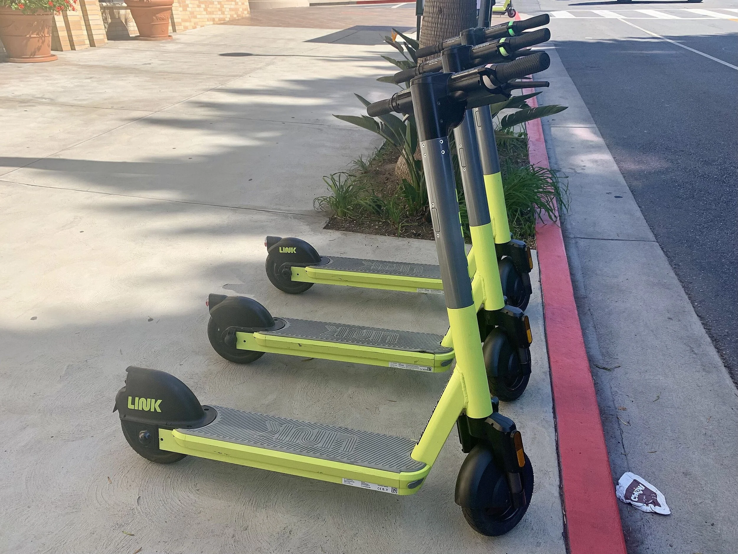
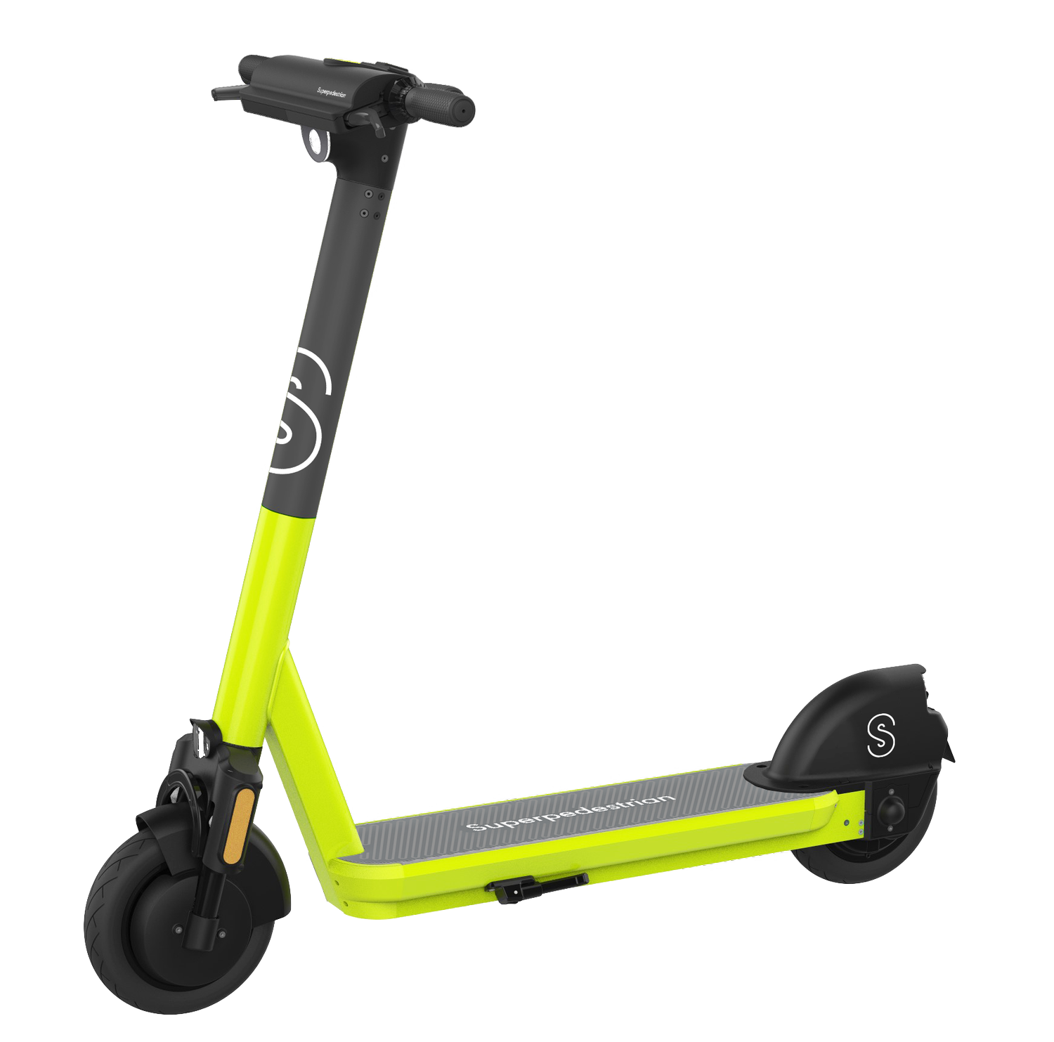
A purpose-built electric scooter for shared fleet use. Designed for safety, robustness, cost and serviceability, this scooter launched in 2019 and tackled major industry issues surrounding user safety and profitability using existing consumer-grade vehicles.
contributions
Vandalism-proof 6061-T6 chassis weldment
IP67-rated motor controller assembly
Mechanical vehicle architecture and removable battery feature integration
Injection molded covers and elastomer deck mat
Integration and management of various COTS/MOTS parts
Top-level assembly and BOM management
DFM and quality liaising with suppliers, including site visits and FAI
Pilot fleet root cause analysis and remediation
quick facts
Lifecycle Phases: Concept Development & Architecture, Detailed Design, Validation, NPI/Tooling, Production Support
Production Quantity: 50k units +
Development Time: 9 months
Range: 60 mi
Top Speed: 20 mph (limited)
System Ingress Rating: IP67
Onboard Connectivity: GPS, Bluetooth, Wifi
chassis weldment
objective
Design a scooter chassis using existing bicycle-industry manufacturing methods which can withstand harsh abuse associated with shared usage, such as jumping off of, or riding down stairsets.
result
objective
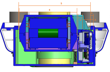
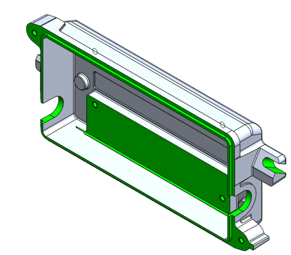
Tolerance stackup of battery and motor controller inside chassis to ensure installation and serviceability
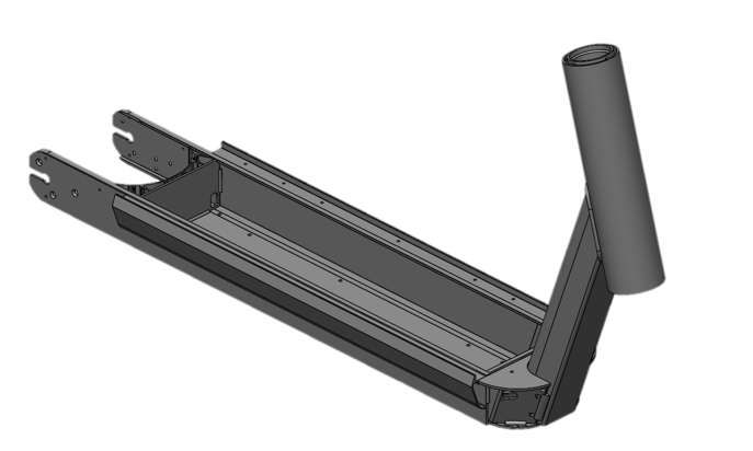
A weldment comprised of 6 custom extrusions, made from 6061 Aluminum was selected for its cost effectiveness and commonality in high-volume bicycle manufacturing . The extruded subcomponents are postmachined, robotically welded, then heat treated to achieve a uniform T6 temper before powdercoating and adding cosmetic finishes. A reinforcement collar added to the neck joint with nearly twice the weld length of other designs prevents failures at this critical joint.
This resulted in a strong, light chassis design that addressed fleet operators’ needs for serviceability and cost-effectiveness, and experienced no major field failures, maximizing user safety. Contemporaneous fleet scooters lasted an average of 3 weeks before decommissioning or disposal, whereas this design was in service for months to years in many cases.
motor controller assembly
Design an environmentally sealed housing for a PCB, with cable exits, thermal transfer paths, and can be replaced as a subassembly.
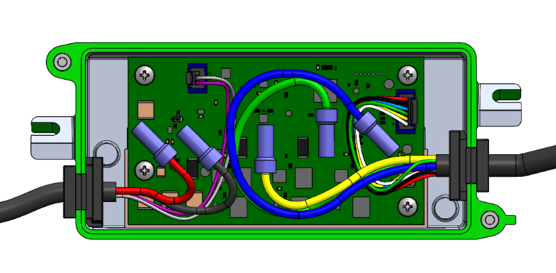
The assembly was submersion tested and met IP67 ingress ratings. The connectorized assembly is easily serviced with the chassis deck removed, and the metal housing provides adequate thermal tdissipation for sustained high-current throughput in the PCB.
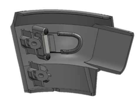
deck trim & chargeport door
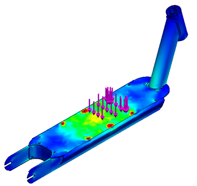
Consumer-grade chassis failure common in early fleet scooters, yield shown in red
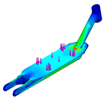
Validated chassis with margin at neck joint
(local concentrations around fasteners do not contribute to failure)
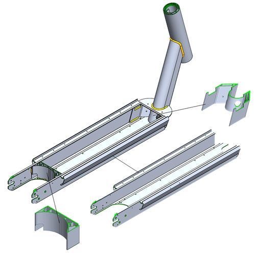
Chassis weldment showing several subcomponents
Robotic welding fixture on manufacturing line
method
Working with an Electrical counterpart, a form factor and PCB footprint was established that would fit inside the chassis and could house all the components needed to transmit around 500W of power between the battery and motor
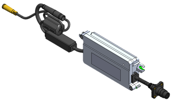
A two-piece semi-solid (SSM) casting of A380 Aluminum constitutes the base and lid of the housing. Custom cables with overmolded seals route power and signal in and out of the box, and a gap pad transmits excess heat from the PCB to the housing, and ultimately to the chassis.
A seal gland designed for RTV sealant or a silicone gasket makes the assembly watertight. The inclusion of a Gore breather vent in the lid allows pressure to equalize in the assembly as temperatures vary.
Overmold bond testing
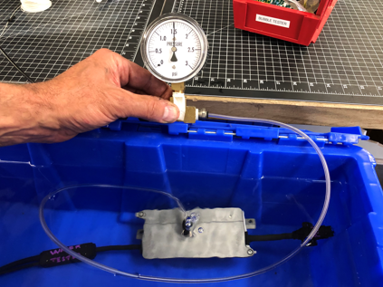
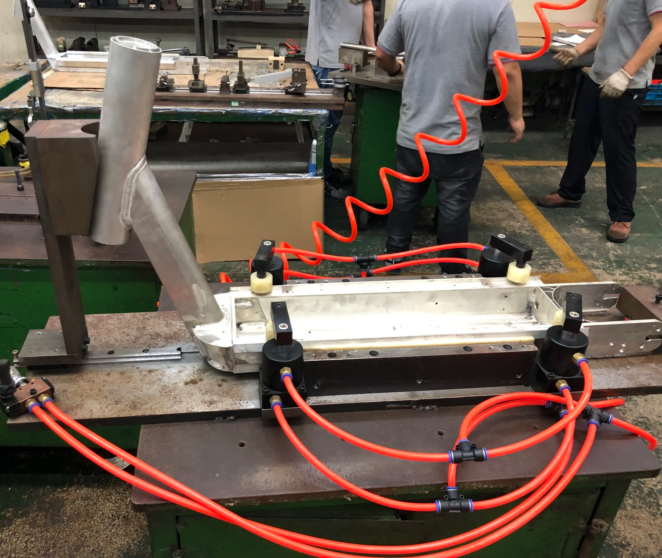
Positive pressure testing for leak paths
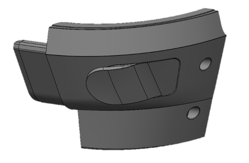
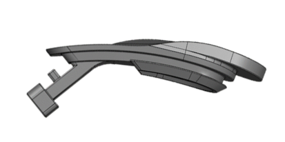
Complex curvature designed for simple two-piece molding resulting in inexpensive, easily replaceable polypropylene parts
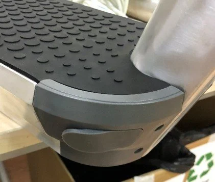
Early tooled part fit check
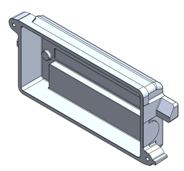
Net Cast Housing Base
method
Using a combination of hand calculations, a data acquisition system with strain gauges, and FEA, a simulation was built to represent the extreme loads on the chassis neck joint.
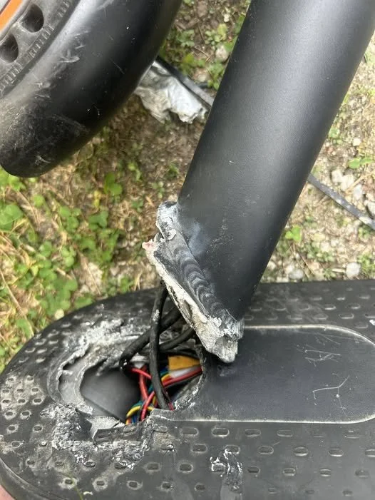
Competitive analysis was conducted on an existing fleet scooter which exhibited failures at this joint, compromising user safety. The simulation accurately reproduced the field failures, and was used as a tool to compare conceptual designs.
Conceptual chassis designs were then generated and iteratively optimized for weight until the simulation showed adequate margin to failure. All welds were modeled with contact sets to accurately simulate load paths between components.
As subsystems which were housed inside the chassis like the battery and motor controller co-evolved, constant cross-functional communication and fit checking took place to ensure compatibility. Features for internal cable routing, component mounting, and tool access were integrated to maximize serviceability and robustness.
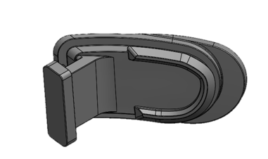
Silicone rubber chargeport door with living hinge and integrated retention features
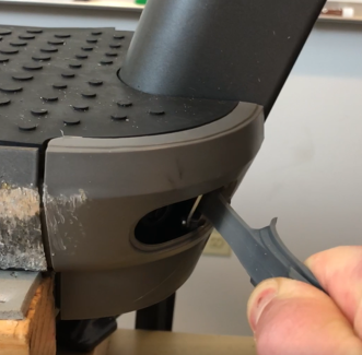
Chargeport door abuse testing
Cables and connectors modeled in place to ensure proper lengths and bend radii
result
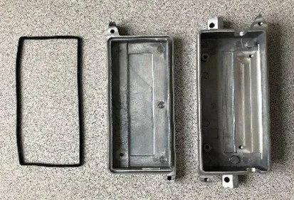
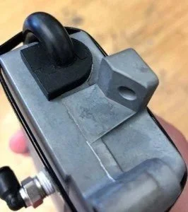
Finished housings with static seal
Postmachined Surfaces